Encryption has been an important field of science ever since communications became prominent. Today, all transfers that occur through the internet are encrypted in some way or the other. A similar requirement to encrypt data transfers exists in embedded systems as well. Typically for such applications, encryption is done in software. The downside of this technique is – it consumes processing time and given that microcontrollers don’t generally have a lot of processing capability, there comes a necessity for hardware based encryption. The current trend of data transfer schemes has no provision for built-in encryption techniques. So if a built-in technique were to be used, these would be its requisites:
- The encryption has to occur with as minimal hardware usage as possible, which will reduce die space during implementation.
- The encryption should be able to secure or abstract the data from external or undesired observers.
- The data should be recovered using least amount of hardware with the highest possible fidelity.
To achieve all these constraints for a hardware based encryption technique, I used the logistic map equation from Chaos theory.
x(n+1) = x(n) * r * [1-x(n)]
If an initial for x(n), between 0 to 1 (other than 0, 0.25, 0.5, 0.75 & 1), is applied to the equation with a suitable coefficient r value as 4, then x(n+1) will be another value between 0 to 1. This x(n+1) will be the next x(n) and the equation iterates. The specialty of this map is that the sequence of x(n) values will look seemingly random. Why? Avoiding the math it suffices to say, It’s chaos.
I used this map and simplified it even further by fixing r=4. If r=4, the map produces chaotic values but in its binary implementation we reduce the need of a multiplier by 1 since multiplying anything by 4 in the binary domain is simple left shifting by two steps and adding zeros. This is similar to decimal multiplication, where multiplying anything by 100 is left shifting by two steps and adding zeros. This results in the following binary chaos map.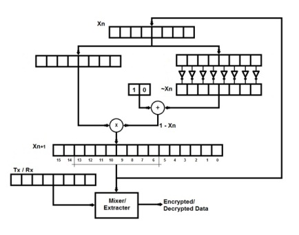
The register at the top contains x(n) values. A bit wise negation of the bits and adding a small offset provides a value equivalent to [1-x(n)] and this is multiplied with x(n). The resulting product is to be left shifted by 2 positions for multiplying by 4. But to avoid left shifting delays, it is more optimized to consider bits 13-6 as x(n+1). Thus the binary map produces chaotic codes which are used to encrypt or decrypt data with a mixer/extractor. A simple mixer/extractor is a bit-wise XOR between the chaotic code and the data.
During development, there were a few issues with how the data transfers would require different code cycling depending on simplex or duplex modes. Irrespective of the transfer modes, the number of nodes to which data is to be transferred, is also important in maintaining sync. This is critical in single master to multiple slaves configurations, as supported by protocols like I2C, SPI etc. For simplicity, I am going to skip the technical details of how these issues are handled. This entire process provides the micro-architecture for embedded chaos.

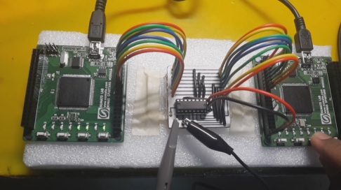
The analytical performance of the technique was verified using python and Matlab and the results were in favor of the idea – a simplified architecture for hardware based encryption. To verify it practically, two Xilinx Spartan 6 FPGA Development boards are used for encryption and decryption. 4 bit data from 4 switches is encrypted into 8 bits and transferred out where the other FPGA decrypts the 4 bit data and drives 4 LEDs accordingly. An interface board with an 8 bit DAC is used to represent the 8 bit encrypted data in an analog form. This analog signal is seen in the computer based digital oscilloscope.
This was my final year project for my Bachelor’s degree in Electronics & Communication engineering. The technique and architecture developed are a suggested prospect for embedded encryption as built-in solution, due to its least hardware requirement. The correlation of the signals and the analysis shows that the message is sufficiently mixed up with a noise like varying-signal (in the analog version) that cannot be decrypted as long as the initial key is not known, ensuring security.